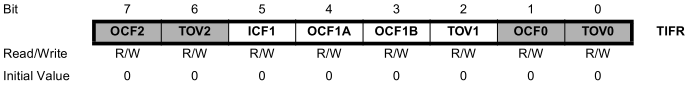
TIFR — TImer Flag Register is used by the Timer/Counter1 subsystem in much the same way as the Timer/Counter0 subsystem.
ICF1 — Input Capture Flag 1.
Set when a capture event occurs on the ICP1 (PORTD6) pin.
OCF1A — Output Compare A Match Flag 1.
Set when a compare match between TCNT1 and OCR1A occurs.
OCF1B — Output Compare B Match Flag 1.
Set when a compare match between TCNT1 and OCR1B occurs.
TOV1 — Timer/Counter1 Overflow Flag.
In normal and CTC modes, set when TCNT1 overflows (goes from 0xffff to 0x0000).
All flags can be cleared two ways:
Manually by writing a logic one to the bit location.
Automatically cleared by hardware when executing the corresponding interrupt handling vector.
TCNT1H and TCNT1L — Timer/CouNTer 1 High and Low registers.
Read and write accessible.
A clock is associated with the register.
Each time the clock ticks, TCNT1H:L are incremented.
When TCNT1H:L goes from 65535 to 0, an overflow flag (TOV1 flag in TIFR) gets set.
We can configure Timer/Counter1 to have 8.39 seconds between overflows (using a prescale factor of 1024).
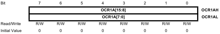
OCR1AH and OCR1AL — Output Compare Register 1 A High and Low registers.
Used in conjunction with OCIE1A (in TIMSK) and OCF1A (in TIFR).
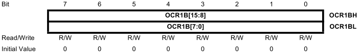
OCR1BH and OCR1BL — Output Compare Register 1 A High and Low registers.
Used in conjunction with OCIE1B (in TIMSK) and OCF1B (in TIFR).
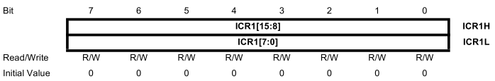
ICR1H and ICR1L — Input Capture Register 1 A High and Low registers.
Used in conjunction with ICES1 (in TCCR1B).
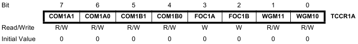
TCCR1A — Timer/Counter1 Control Register A. (see pp. 105-107 of the ATmega32 Data Sheet)
COM1A1:0 — Compare Output Mode for Channel A. * COM1B1:0 — Compare Output Mode for Channel B.
FOC1B — Force Output Compare for Channel B.
WGM11:0 — Waveform Generation Mode.
For input capture mode, TCCR1A = 0x00.
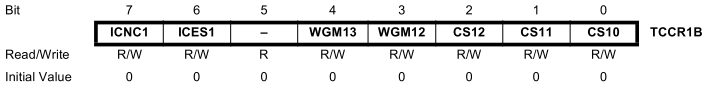
TCCR1B — Timer/Counter1 Control Register B. (see pp. 108-109 of the ATmega32 Data Sheet)
ICNC1 — Input Capture Noise Canceler (active high). We will leave this low.
ICES1 — Input Capture Edge Select.
1 — rising edge.
0 — falling edge.
When a capture is triggered, the counter value in TNCR1H:L is copied to ICR1H:L.
CS12:0 — Clock Select bits.
These are the same as the CS02:0 clock select options (except the external clock source is T1 instead of T0).
Note: There is an error in the clock select table on p. 31 of ATmega32 Reference Guide. The description from CS12:0 = 101 should be "clk/1024 (From prescaler)".
WGM13:2 — Waveform Generation Mode.
These, combined with WGM11:0 from TCCR1A select the mode of operation for the Timer/Counter1 subsystem.
With WGM11:0 = 00, the modes of operation available are:
WGM13
WGM12
Mode of Operation
TOP
Update of OCR1x
TOV1 Flag Set
0
0
Normal
0xFFFF
Immediate
MAX
0
1
CTC
OCR1A
Immediate
MAX
1
0
PWM, Phase and Freq Correct
ICR1
BOTTOM
BOTTOM
1
1
CTC
ICR1
Immediate
MAX
Sample Code
Measure Waveform Period with Input Capture
Suppose we wanted to measure the period of an arbitrary square wave.
Create a firstEdge flag.
Initialize stack, interrupts, etc...
; ISR for input capture pin with Timer/Counter1 Subsystem
; This ISR assumes that the following data memory reservations have been made:
;   firstFlagLoc -- 1 byte
;   periodLoc -- 2 bytes
;   firstTimeLoc -- 2 bytes
timeCaptureISR:
.def temp = r16
.def firstFlag = r17
     push  temp
     in    temp, SREG
     push  temp
     push  r0
     push  r1
     push  r2
     push  r3
     lds   firstFlag, firstFlagLoc
     tst   firstFlag
     brne  secondEdge
     in    r0, ICR1L                ; Must read low byte first
     in    r1, ICR1H
     sts   firstTimeLoc, r0
     sts   firstTimeLoc+1, r1
     rjmp  tcISRdone
secondEdge:
     in    r2, ICR1L
     in    r3, ICR1H
     lds   r0, firstTimeLoc
     lds   r1, firstTimeLoc+1
     sub   r2, r0                   ; Subtract low byte
     sbc   r3, r1                   ; Subtract high byte
     sts   periodLoc, r2
     sts   periodLoc+1, r3
tcISRdone:
     com   firstFlag
     sts   firstFlagLoc, firstFlag
     pop   r3
     pop   r2
     pop   r1
     pop   r0
     pop   temp
     out   SREG, temp
     pop   temp
     reti