ATmega32 Architecture
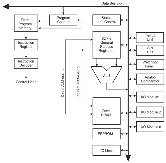
The ATmega32 microcontroller has the following architecture:
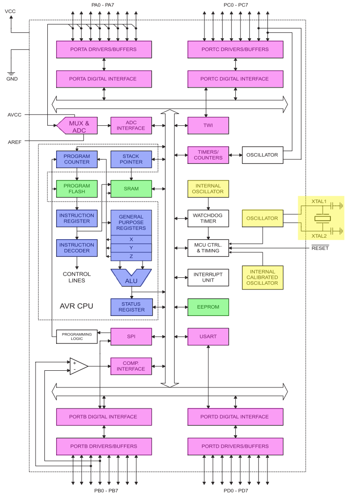
- The CPU components are shaded blue.
- The memory components are shaded green.
- The clock components are shaded in orange.
- The I/O components are shaded in purple.
ATmega32 Highlights
- Native data size is 8 bits (1 byte).
- Uses 16-bit data addressing allowing it to address 216 = 65536 unique addresses.
- Has three separate on-chip memories
- 2KiB SRAM
- 8 bits wide
- used to store data
- 1KiB EEPROM
- 8 bits wide
- used for persistent data storage
- 32KiB Flash
- 16 bits wide
- used to store program code
- 2KiB SRAM
- I/O ports A-D
- Digital input/output
- Analog input
- Serial/Parallel
- Pulse accumulator
Before we get into the details, let's look at the programmers model to help motivate our desire to better understand the internals of the ATmega32 microcontroller.
Programmers Model
- languages like C, C++, and Java require little, if any, knowledge of the CPU's internal configuration.
- Assembly language requires knowledge of the internals of the CPU since we are operating at a lower level.
- Machine language is the native language of the CPU
- Consists only of 1's and 0's.
- Is what we actually download to the controller's program memory.
- Is stored in the .hex file generated by AVR studio.
- Program hierarchy:
- High-level language gets converted into assembly language by a compiler.
- Assembly language gets converted into machine language by an assembler.
- AVR Studio acts as our assembler for this course.
- For CE2800, we will be writing programs in assembly language.
- In CE2810 we will write programs/functions in C and use a GNU compiler to compile those programs/functions into assembly.
CPU and Registers
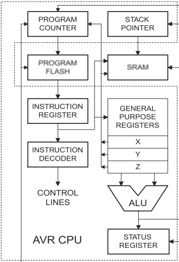
Steps to execution
- Program Counter fetches program instruction from memory
- The PC stores a program memory address that contains the location of the next instruction.
- The PC is initialized to 0x0 on reset/power up.
- When we placed the bootloader on the chip, we set a fuse that enables a reset vector to load the PC with the address where the bootloader program starts.
- When the program begins, the PC must contain the address of the first instruction in the program.
- Program instructions are stored in consecutive program memory locations.
- The PC is automatically incremented after each instruction.
- Note: There are jump instructions that can modify the PC (e.g., the PC must change when calling or returning from some other routine).
- Places instruction in Instruction Register.
- Instruction Decoder determines what the instruction is.
- Arithmetic Logic Unit executes the instruction.
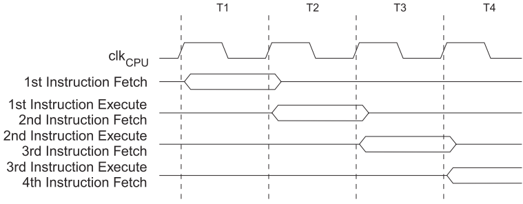
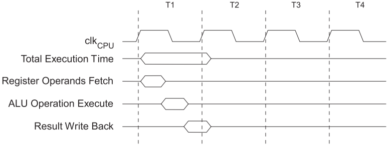
The CPU clock determines the timing of when instructions are fetched and executed:
Registers
- Directly accessed by the CPU/ALU — very fast.
- Registers contain:
- Address of the next instruction to fetch from program memory (PC).
- Machine instruction to be executed (IR).
- "Input" data to be operated on by the ALU.
- "Output" data resulting from an ALU operation.
General Purpose Registers
- There are 32 8 bit general purpose registers, R0-R31.
- X, Y, and Z are 16 bit registers that overlap R26-R31.
- Used as address pointers.
- Or to contain values larger than 8 bits (i.e., >255).
- Only register Z may be used for access to program memory.
- Certain operations cannot be performed on the first 16 registers, R0-R15
- LDI
- ANDI
- etc...
- CLR Rx does work on all registers.
Other Registers
- Stack pointer (SP)
- Is 16 bits wide.
- Stores return address of subroutine/interrupt calls.
- May be used to store temporary data and local variables.
- Status Register (SREG)
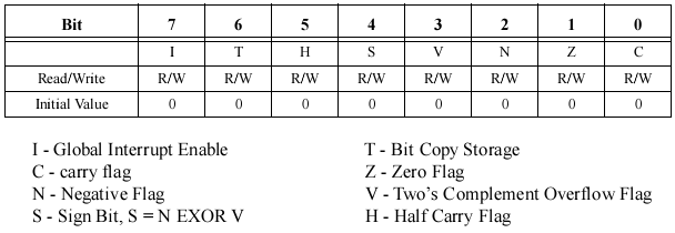
- Is 8 bits wide.
- Contains information associated with the results of the most recent ALU operation.
- Carry flag (C) set if CY from most signficant bit (MSB).
- Often used when adding numbers that are larger than 8 bits. Here we need to use an add with carry instruction (ADC) to add the next most significant byte.
- Zero flag (Z) set if result is zero.
- BREQ instruction says branch if zero flag is set.
- BRNE instruction says branch if zero flag is not set.
- Negative flag (N) set if MSB is one.
- Arithmetic instructions change the flags
- Data transfer instructions do not change the flag.
- The instruction set documentation identifies which flags each instruction may modify.
- Overflow flag (V) set if 2's complement overflow occurs.
- An overflow occurs if you get the wrong sign for your result, e.g., 6410 + 6410 = -12810 (010000002 + 010000002 = 100000002).
- Note: whenever the carry into the MSB and the carry out don't match, we have an overflow.
- Sign bit (S) s = N EXOR V.
- Half carry flag (H) is set when carry occurs from b3 to b4.
- Used with binary coded decimal (BCD) arithemtic.
- Carry flag (C) set if CY from most signficant bit (MSB).
Memory
- The address bus is 16 bits wide.
- The data bus is 8 bits wide.
- Program memory is stored on Flash from 0x0000 to 0x3FFF (F_END).
- Our boot loader is loaded in the last 1KiB of the Flash memory.
- SRAM is used for:
- 32 General Purpose registers from 0x00 to 0x1F.
- 64 I/O ports from 0x20 to 0x5F.
- User data from 0x60 to 0x85F (RAMEND).
- Note: the bootloader uses the last 32 bytes of data memory, we will consider RAMEND-0x20 as the end of data RAM.
- ROM for user data is stored on EEPROM.
- ATmega32 has 1KiB of storage from 0x000 to 0x3FF (E_END).
Reference Material
You should read pp. 3-13 of the ATmega32 Specification.