Based on HD44780 LCD controller. (See Hitachi LCD Documentation)
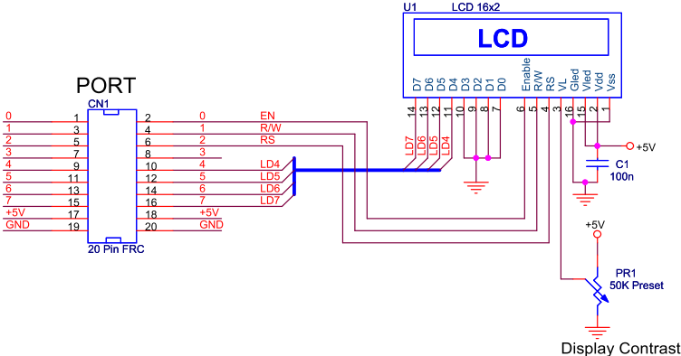
- Block Diagram
- E — enable
- Located at lcdPORT0 on SunRom LCD panel.
- R/W — read/write (1 — read, 0 — write)
- Located at lcdPORT1 on SunRom LCD panel.
- RS — register select
- Located at lcdPORT2 on SunRom LCD panel.
- Data — 8 data bits
- The data bits are bidirectional, but rarely is there a need to read from it.
- On SunRom LCD panel D[7..4] connected to lcdPORT[7..4] and D[3..0] connected to ground.
- E — enable
- There are two types of information that can be written to the data pins:
- Data (RS should be set (high)).
- Command (RS should be cleared (low)).
- A few useful commands:
- clear — clears the display.
- home — move cursor to home (first) position.
- blink — cursor blinks.
- auto-increment cursor position.
LCD Commands
Table 6 from the HD44780 datasheet lists the set of available instructions:
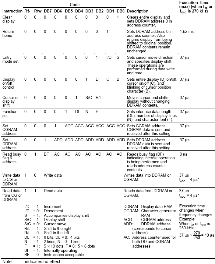
A number of instructions have parameters specified by one to three letters.
- Function Set
- DL — specifies the interface data length
- 0 — 4-bit mode.
- 1 — 8-bit mode.
- N — specifies the number of lines for the display
- 0 — 1-line display.
- 1 — 2-line display.
- F — specifies the font used
- 0 — 5 x 8 dot character font
- 1 — 5 x 10 dot character font
- DL — specifies the interface data length
- Display On/Off Control
- D — display on/off flag
- 0 — display off.
- 1 — display on.
- C — cursor on/off flag
- 0 — cursor off.
- 1 — cursor on.
- B — blinking on/off flag
- 0 — blinking off.
- 1 — blinking on.
- D — display on/off flag
- Entry Mode Set
- I/D — Increment/Decrement cursor by 1 on data read/write flag
- 0 — moves cursor position to right by one character after reading/writing character from/to current position.
- 1 — moves cursor position to left by one character after reading/writing character from/to current position.
- S — display shift
- 0 — disabled.
- 1 — enables shifting of data so that current data moves right and new data takes the home position.
- I/D — Increment/Decrement cursor by 1 on data read/write flag
Writing Commands to the LCD
- The LCD has both a 4-bit and 8-bit mode.
- Since D[3..0] are connected to ground on the SunRom LCD panel, we must use the 4-bit communication mode.
- However, the LCD defaults to 8-bit mode.
- Therefore, the first command must be sent in 8-bit mode, and that command should instruct the LCD to operate in 4-bit mode.
Generic Command Write Process in 4-bit Mode
- Output upper nibble of command to lcdPORT
- Set E
- Delay for four cycles
- Clear E
- Delay for 2ms
- Output lower nibble of command to lcdPORT
- Set E
- Delay for four cycles
- Clear E
- Delay for 2ms
- Set RS
- Set R/W
- Delay for 2ms
We can write 4 bits to the LCD as follows:
; lcd_cmd_write_nibble PRELIMINARY VERSION
; Purpose: write 4-bits of a command to the LCD display
; Parameters:
;   r24 -- upper nibble contains the 4 bits to be written to the LCD display
; Assumes .equ directive has set lcdPORT to the appropriate I/O port
; Dependencies: delay2ms (found in delay.asm)... you'll need to write this.
lcd_cmd_write_nibble:
      push    r24              ; store register values

      andi    r24, 0xF0        ; strip off lower 4 bits

      out     lcdPORT, r24     ; write nibble to LCD display
      sbi     lcdPORT, 0       ; set E (enable LCD)

      nop                      ; delay 4 cycles
      nop
      nop
      nop

      cbi     lcdPORT, 0       ; clear E (latch cmd/data being written to LCD display)
      rcall   delay2ms         ; found in delay.asm

      pop     r24              ; restore register values
      ret
; end lcd_cmd_write_nibble
- Provided we load R24 with the appropriate values, the lcd_write_nibble1 subroutine does steps 1-5 and 5-10.
- We can perform the entire generic command write process in 4-bit mode by making use of lcd_write_nibble1 and the subroutine below:
; lcd_cmd_write1 PRELIMINARY VERSION
; Purpose: Sends command to the LCD display
; Parameter:
;   r24 -- cmd/data to be written to the LCD display
; Assumes .equ directive has set lcdPORT to the appropriate I/O port
; Dependencies: lcd_write_nibble1
lcd_cmd_write1:
      push    r24              ; store register value

      rcall   lcd_cmd_write_nibble; write upper nibble to lcd
      swap    r24              ; swap upper and lower nibbles
      rcall   lcd_cmd_write_nibble; write what was originally the lower nibble to lcd
      sbi     lcdPORT, 2       ; set RS (data mode)
      sbi     lcdPORT, 1       ; set R/W (read mode)

      pop     r24              ; restore register value
      ret
; end lcd_cmd_write1
Initializing LCD to 4-bit Mode
Figure 24 from the HD44780 datasheet describes the procedure for initializing the LCD to use the 4-bit interface:
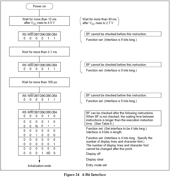
We can approximate the datasheet instructions by calling lcd_cmd_write1 with the following:
- 0x33 — Function set to 8-bit mode.
- insert additional 2ms delay after first command write.
- 0x32 — Function set to 8-bit mode again.
- 0x28 — Set function to 4-bit mode, indicate LCD has two lines.
- 0x0F — Turn display on, cursor on and blink cursor.
- 0x01 — Clear display.
- 0x06 — Sets Entry Mode to auto-increment cursor and disable shift mode.
- 0x02 — send the cursor to the home position.
Writing Data to the LCD
- The process of writing data to the LCD is identical to writing commands except that the RS flag must be set instead of cleared.
- As a result:
- The lcd_data_write1 subroutine would be identical to lcd_cmd_write1 except we would call lcd_data_write_nibble instead of lcd_cmd_write_nibble.
- The lcd_data_write_nibble would be identical to lcd_cmd_write_nibble except that we would insert ORI r24, 0x04 after the line with the ANDI instruction in order to set the RS flag.
- Since this would be duplicating a significant portion of code, I've chosen to use a register to indicate whether the byte should be written as a command or as data.
; CE-2800 lcdlib.asm
; Purpose: This file contains a collection of utility subroutines
;          used for controlling the LCD display.
;
; Author: t a y l o r@msoe.edu, 01-10-2008
;
; Usage: It is intended that this file be included at the end of
;        the .asm file that makes use of the subroutines found in
;        this file.
;        In addition to including lcdlib.asm, two .equ directives
;        must be added to specify the PORT to which the LCD is
;        connected.  For example, if the LCD panel is connected
;        to PORTB, the following lines should be included:
;
;        .equ lcdPORT = PORTB
;        .equ lcdDDR = DDRB
;        .include "lcdlib.asm"
;
; Subroutines Provided:
;   lcd_port_config -- Initializes the ATmega32 port used by the LCD display
;
;   lcd_init -- Initializes the LCD display
;
;   lcd_cmd_write -- Sends a command to the LCD display
;       Parameter: r24 -- data to be written to the LCD display
;
;   lcd_data_write -- Sends a byte of data to the LCD display
;       Parameter: r24 -- data to be written to the LCD display
;
;   lcd_clear -- Clear the LCD display and home cursor
;
;   lcd_string_write -- Display a message on the LCD screen
;       Parameter: Z -- byte address of beginning of message
;
; Dependencies: Requires "delay.asm"

.cseg
; lcd_port_config
; Purpose: Initializes the ATmega32 port used by the LCD display
lcd_port_config:
    ;
    ; Left as an exercise for the diligent student
    ;
; end lcd_port_config


; lcd_init
; Purpose: Initialize the LCD display
; Dependencies: lcd_cmd_write
lcd_init:
    ;
    ; Left as an exercise for the diligent student
    ;
; end lcd_init


; lcd_cmd_write
; Purpose: Sends a command to the LCD display
; Parameter:
;   r24 -- command to be written to the LCD display
; Dependencies: lcd_write
; Author: t a y l o r@msoe.edu, 01-10-2008
lcd_cmd_write:
      push    r22              ; store register value

      clr     r22              ; clear r22 to tell lcd_write to use command mode
      rcall   lcd_write

      pop     r22              ; restore register value
      ret
; end lcd_cmd_write


; lcd_data_write
; Purpose: Sends a byte of data to the LCD display
; Parameter:
;   r24 -- data to be written to the LCD display
; Dependencies: lcd_write
; Author: t a y l o r@msoe.edu, 01-10-2008
lcd_data_write:
      push    r22              ; store register value

      ser     r22              ; sets r22 to tell lcd_write to use data mode
      rcall   lcd_write

      pop     r22              ; restore register value
      ret
; end lcd_data_write


; lcd_write
; Purpose: Sends cmd/data to the LCD display
; Parameter:
;   r24 -- cmd/data to be written to the LCD display
;   r22 -- 0b-------0 for command mode, 0b-------1 for data mode (- means don't care)
; Dependencies: lcd_write_nibble
; Author: t a y l o r@msoe.edu, 01-10-2008
; Note: Not documented at top of file since this is a helper subroutinue
lcd_write:
      push    r24              ; store register value

      rcall   lcd_write_nibble ; write upper nibble to lcd
      swap    r24              ; swap upper and lower nibbles
      rcall   lcd_write_nibble ; write what was originally the lower nibble to lcd
      sbi     lcdPORT, 2       ; set RS (data mode)
      sbi     lcdPORT, 1       ; set R/W (read mode)

      pop     r24              ; restore register value
      ret
; end lcd_write


; lcd_write_nibble
; Purpose: write 4-bits to the LCD display (either command or data)
; Parameters:
;   r24 -- upper nibble contains the 4 bits to be written to the LCD display
;   r22 -- 0b-------0 for command mode, 0b-------1 for data mode (- means don't care)
; Dependencies: delay2ms (found in delay.asm)
; Author: t a y l o r@msoe.edu, 01-10-2008
; Note: Not documented at top of file since this is a helper subroutinue
lcd_write_nibble:
      ; store register values
      push    r24
      push    r22

      andi    r24, 0xF0        ; strip off lower 4 bits

      ; Set RS=1 if in data mode, otherwise leave RS=0
      sbrc    r22, 0           ; skip next line if in CMD mode (r22=0b-------0)
      ori     r24, 0x04        ; set RS (in data mode)

      out     lcdPORT, r24     ; write nibble to LCD display
      sbi     lcdPORT, 0       ; set E (enable LCD)

      nop                      ; delay 4 cycles
      nop
      nop
      nop

      cbi     lcdPORT, 0       ; clear E (latch cmd/data being written to LCD display)
      rcall   delay2ms

      ; restore register values
      pop     r22
      pop     r24
      ret
; end lcd_write_nibble

; lcd_clear
; Purpose: Clear the LCD display and home cursor
; Dependencies: lcd_cmd_write
lcd_clear:
    ;
    ; Left as an exercise for the diligent student
    ;
; end lcd_clear


; lcd_string_write
; Purpose: Display a message on the LCD screen
; Parameter:
;   Z -- byte address of beginning of message
; Dependencies: lcd_data_write
lcd_string_write:
    ;
    ; Left as an exercise for the diligent student
    ;
; end lcd_string_write

.include "delay.asm"
Missing Pieces
You should be able to write subroutines for:
- delay2ms — delay for two milliseconds and store that subroutine in a file called delay.asm
- lcd_init — sends a sequence of initialization commands to LCD.
- lcd_port_init — configures ports used by LCD.
- lcd_string_write — write the null terminated string stored in program memory (indicated by the Z pointer) to the LCD.
- lcd_clear — clears the LCD screen.